
Steering, Wheels, Column, etc


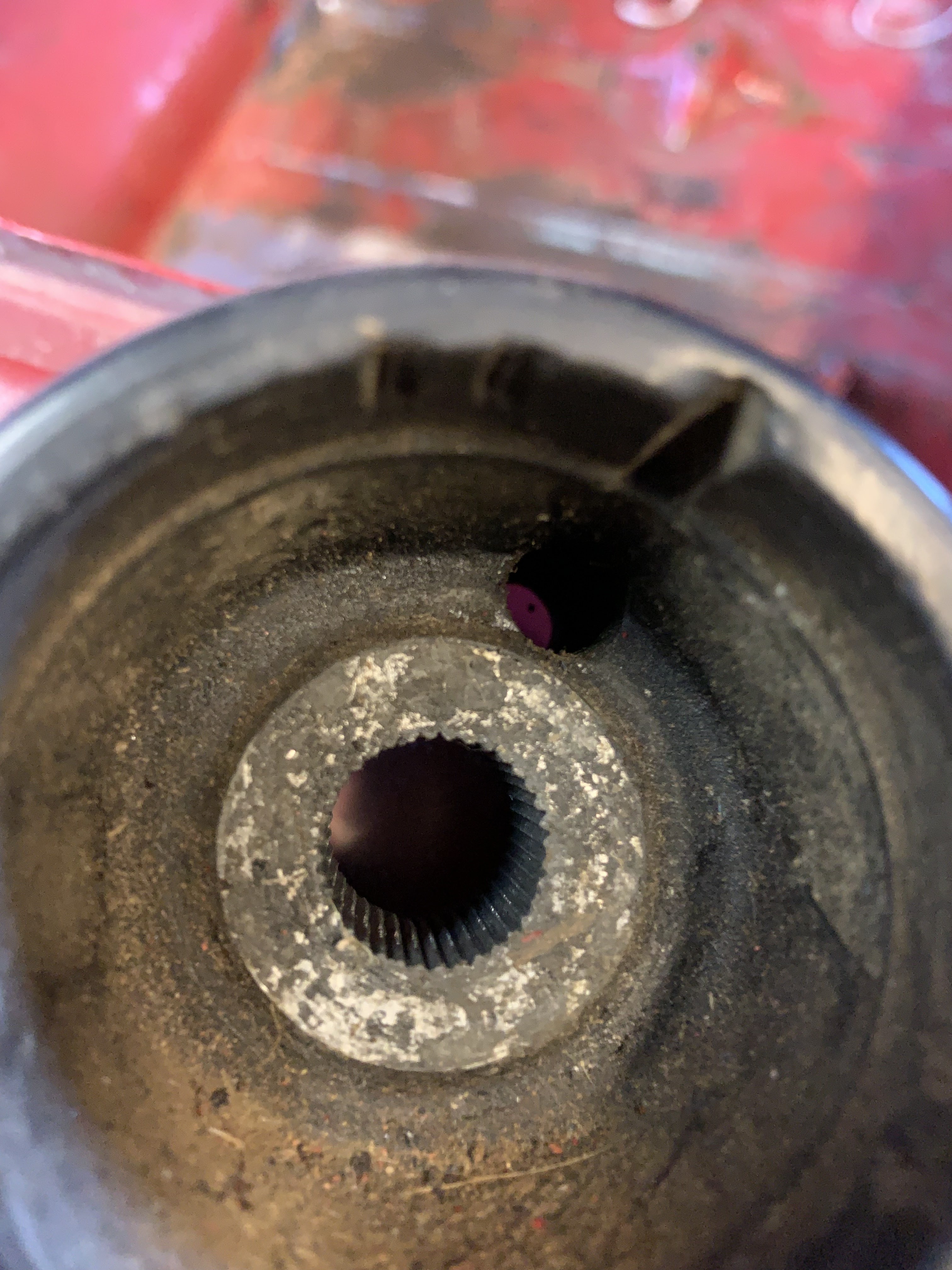
So Barnaby arrived with an early wheel (like the one pictured above)  that is almost certainly not original.  based on the info I've found online, its hub should not be compatible with the '68 '69' steering shaft. (the hub on this wheel fits the shaft, and the shaft - apparently - is correct for the car.) 


***  Turns out this info was wrong and the earliest cars had the same shaft diameter and spline count as the '68-69.  ****  

Regardless, the wheel is pretty beat up, and I am fond of the banjo-spoke type (below) particular to the 68/69 mode years.


 The splined and threaded portions of the steering shaft vary by year, apparently as follows:

Steering column splines for both MGB and Midgets: 
58-61

spline 5/8 by 36 splines 

62-67 
spline 3/4 by 48 splines 
thread 11/16 X 27 TPI 

68-69 
spline 5/8 by 36 splines 
thread 9/16 X 27 TPI 


70-80 
spline 11/16 by 36 splines 
thread 9/16 X 18 TPI


And here are the column switches 


Notice below, same switch, two different stalk lengths.  
Unfortunately, The cowl and column switches were disassembled when I bought the car and the right hand side of the cowl is missing. 


Comments

Popular posts from this blog

Front frame repair

Heavy metal stories... As mentioned in a previous post the front frame was in worse shape than I'd imagined. You can see in the photos below and elsewhere the bent frame rail and steering rack mounting beam, plus the really bad work on the front chassis horns.    The painful kink in the frame rail. Fortunately, a few very kind folks took the time to explain to me how to approach this sort of a frame repair. So, I bought a "portapower" on sale, and a frame clamp and followed the Eugene's directions. And slowly, carefully, was able to pull the frame mostly straight.   Amazing! A great first step. I also used a large C clamp to bring the box section back into square as it had been moved into a parallelogram shape at the site of the bend. As detailed in another post, I was able to salvage he front half of a parts car. Thanks for your generosity Ken!  From this I cut some repair pieces required for Miguela. So far, the steering rack x-member and a section of frame.   Re

Front End Fact Find

June 15 - confirmed that the chassis is not bent!  Plumb bob and chalk lines. See section R page 18 of the Bentley manual for dimensions and method.   Update June 12 - more photos of frame  Update -  Obvious accident damage and clearly the frame horns are not as they should be.  Measurement and verification required.  The photo below is rather telling. The horns should be 12” apart (11” between the flanges), parallel to the car’s centreline and level and straight with respect to its the frame rail.  I am not certain precisely how far each  horn should extend from the crossmember. I will assume but should verify that the rad uprights are at 90deg to the horn, and should verify the height of the rad support above the horn. the threaded bosses for the grill shroud (2 in each horn, 3 in each rad upright) are the most critical location points with respect to hood alignment, as these locate the front end assembly. Straight edge clamped to frame rail. Left side horn is straight. Right side ho

Engine bay dissasembly - reference photos

  Firewall area