
Front frame repair

Heavy metal stories...


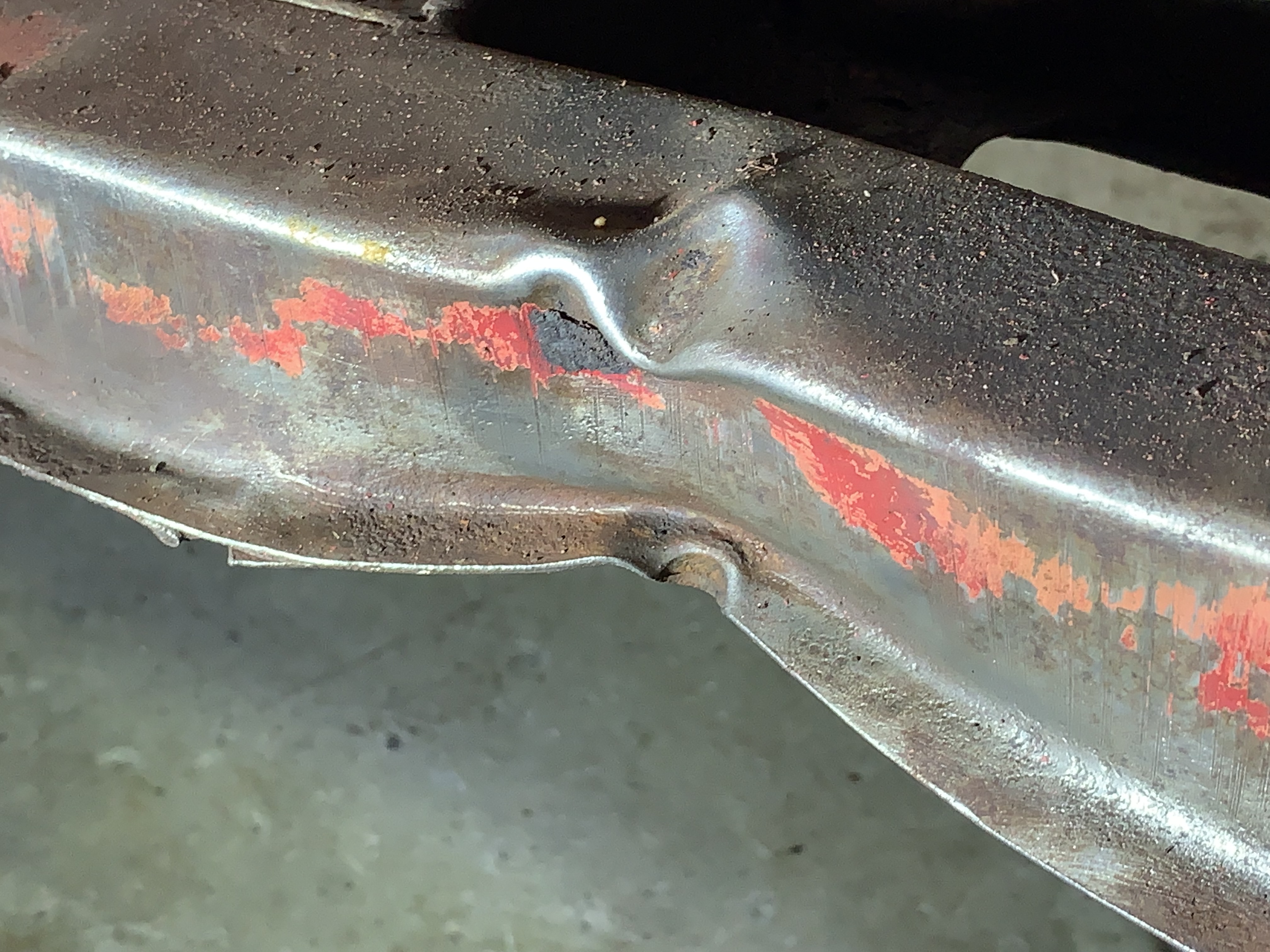
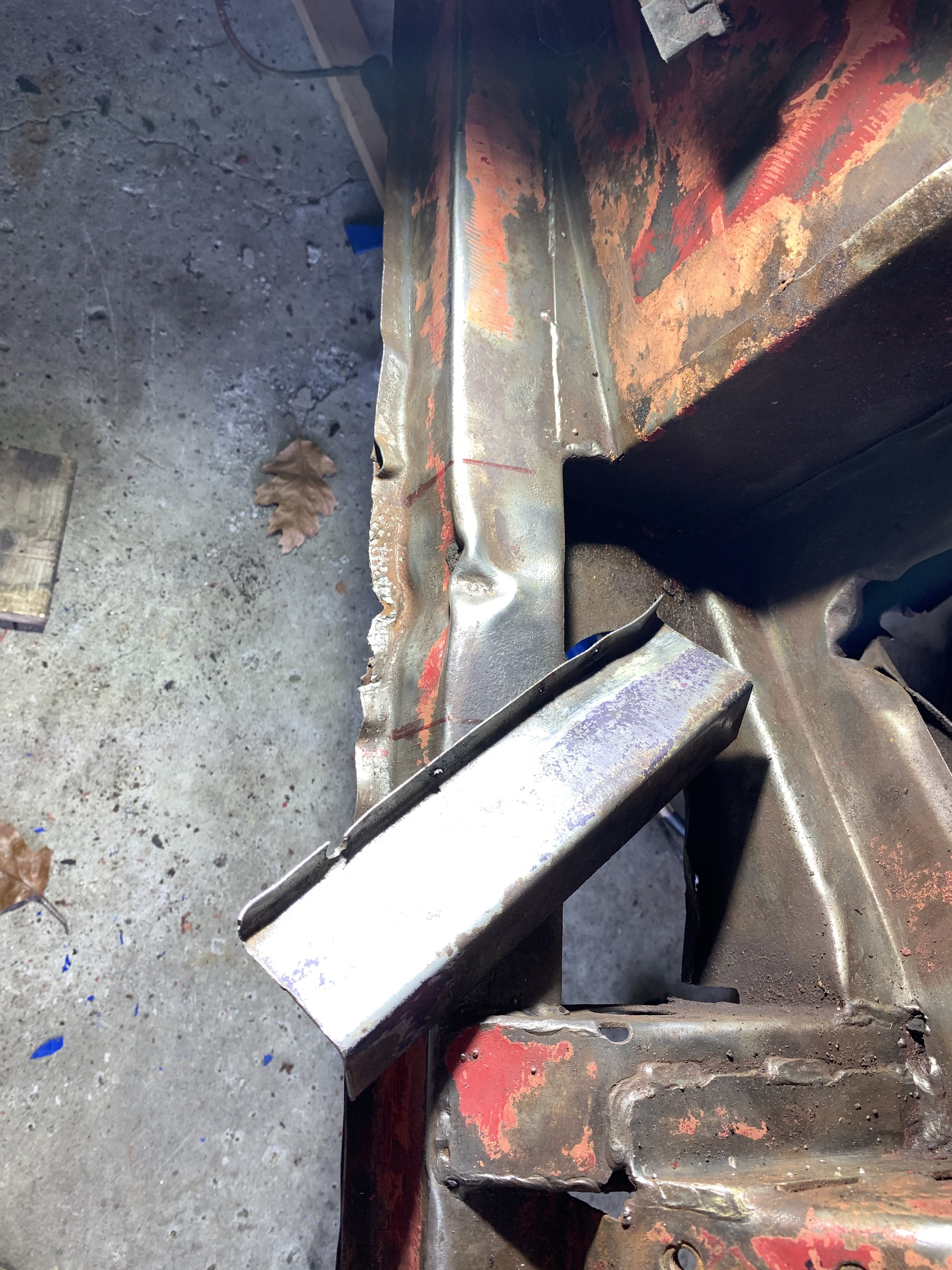
As mentioned in a previous post the front frame was in worse shape than I'd imagined. You can see in the photos below and elsewhere the bent frame rail and steering rack mounting beam, plus the really bad work on the front chassis horns.   
The painful kink in the frame rail.


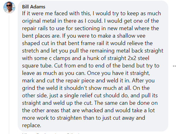
Fortunately, a few very kind folks took the time to explain to me how to approach this sort of a frame repair.


So, I bought a "portapower" on sale, and a frame clamp and followed the Eugene's directions.

And slowly, carefully, was able to pull the frame mostly straight.   Amazing! A great first step.


I also used a large C clamp to bring the box section back into square as it had been moved into a parallelogram shape at the site of the bend.

As detailed in another post, I was able to salvage he front half of a parts car. Thanks for your generosity Ken!  From this I cut some repair pieces required for Miguela. So far, the steering rack x-member and a section of frame.


Replacement atop damaged original.

The frame section was further trimmed to make a repair part for the recently straightened section

At this point, I was hesitant to commit to this repair, and I procrastinated as I pondered various ways to approach it.  Eugene's description of pulling would have me welding tabs onto the frame and thoughtfully straightening the remaining kinks, (probably the best and most rewarding approach) while others would have simply cut out the old and welded-in new frame sections or angles and moved on.  Finally, I decided to cut out only the worst of the remaining crease, retaining  as much original metal as possible and use my repair piece to overlap  the damaged section of frame, plug, lap, and seam welding it in place.  My hope was to get a very strong and professional looking (though detectable) repair.   This was instead of attempting a perfect fitment and perfect butt welds of a flush repair piece, as welding such a repair is likely beyond my currently skill level.        


Comments

Popular posts from this blog

Front End Fact Find

June 15 - confirmed that the chassis is not bent!  Plumb bob and chalk lines. See section R page 18 of the Bentley manual for dimensions and method.   Update June 12 - more photos of frame  Update -  Obvious accident damage and clearly the frame horns are not as they should be.  Measurement and verification required.  The photo below is rather telling. The horns should be 12” apart (11” between the flanges), parallel to the car’s centreline and level and straight with respect to its the frame rail.  I am not certain precisely how far each  horn should extend from the crossmember. I will assume but should verify that the rad uprights are at 90deg to the horn, and should verify the height of the rad support above the horn. the threaded bosses for the grill shroud (2 in each horn, 3 in each rad upright) are the most critical location points with respect to hood alignment, as these locate the front end assembly. Straight edge clamped to frame rail. Left side horn is straight. Right side ho

Engine bay dissasembly - reference photos

  Firewall area